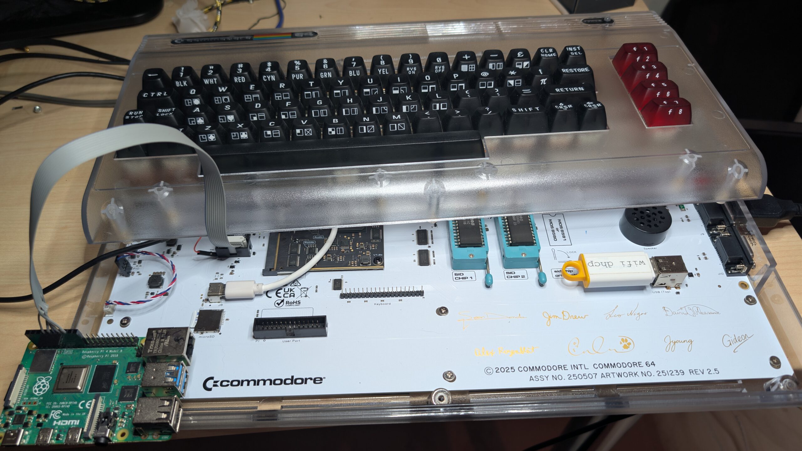
So this happened: I bricked my Commodore 64 Ultimate flashing a custom firmware build I’d put together off Gideon’s master. Not a hard brick — networking stayed up and the management menu was reachable — but BASIC handoff was permanently broken, and the in-menu update flow that would normally let me flash a known-good build back quietly failed every time. Through-the-front-door recovery wasn’t available.
The good news: Gideon Zweijtzer (the C64U’s designer) ships an official JTAG recovery procedure for exactly this situation. The not-so-good news: it requires an FT232H USB-MPSSE adapter, and I didn’t have one on the desk. Mouser delivery would be 2–5 days, and Friday was Vappu (Finnish May Day) so even slower.
I had a different option, though. I already had a Raspberry Pi wired up as a Xilinx JTAG programmer for some unrelated FPGA work. JTAG is JTAG — at the protocol level, the Pi’s GPIO can do exactly what an FT232H can do, just slower. So I ported Gideon’s recovery script to the Pi.
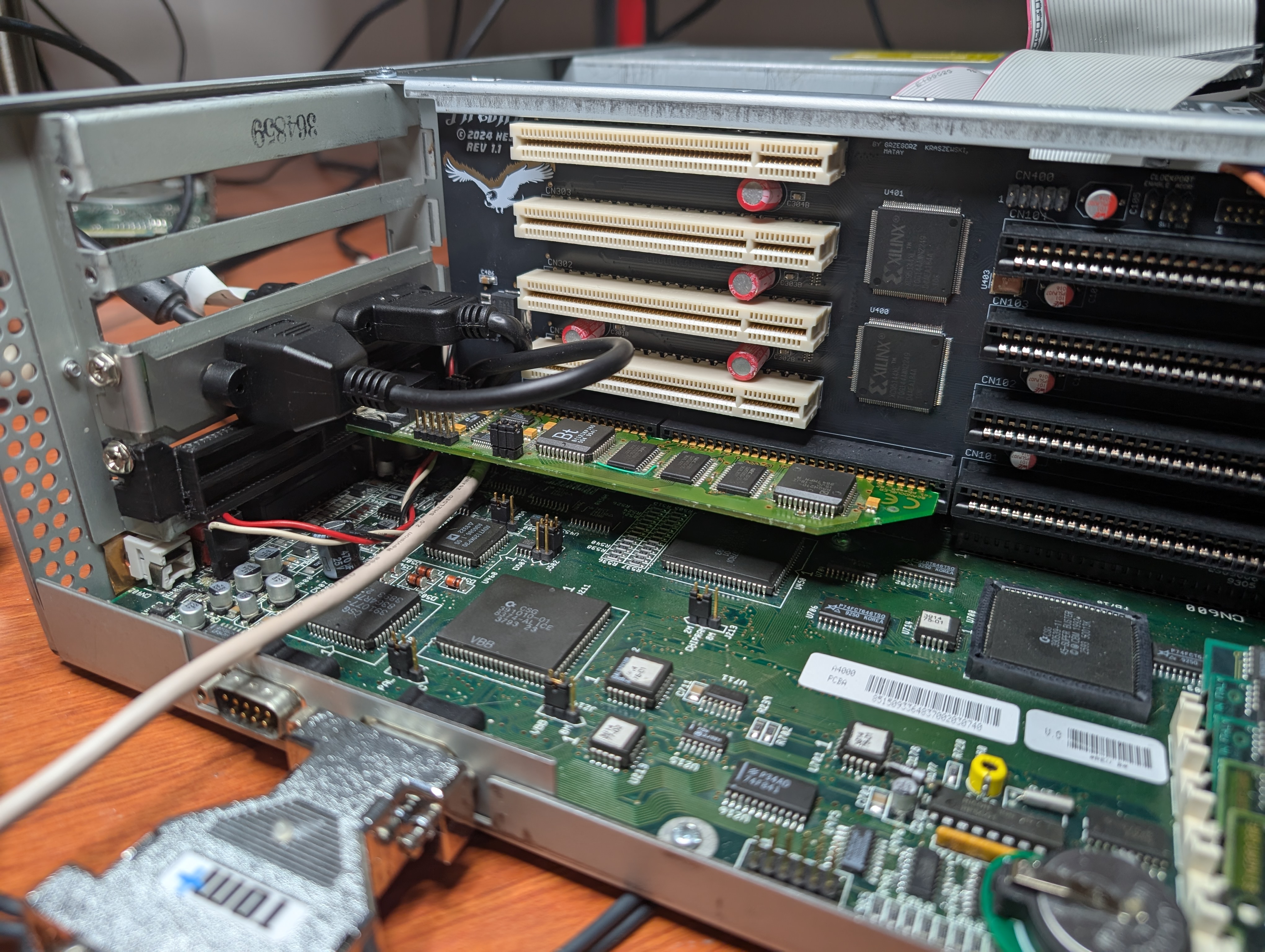
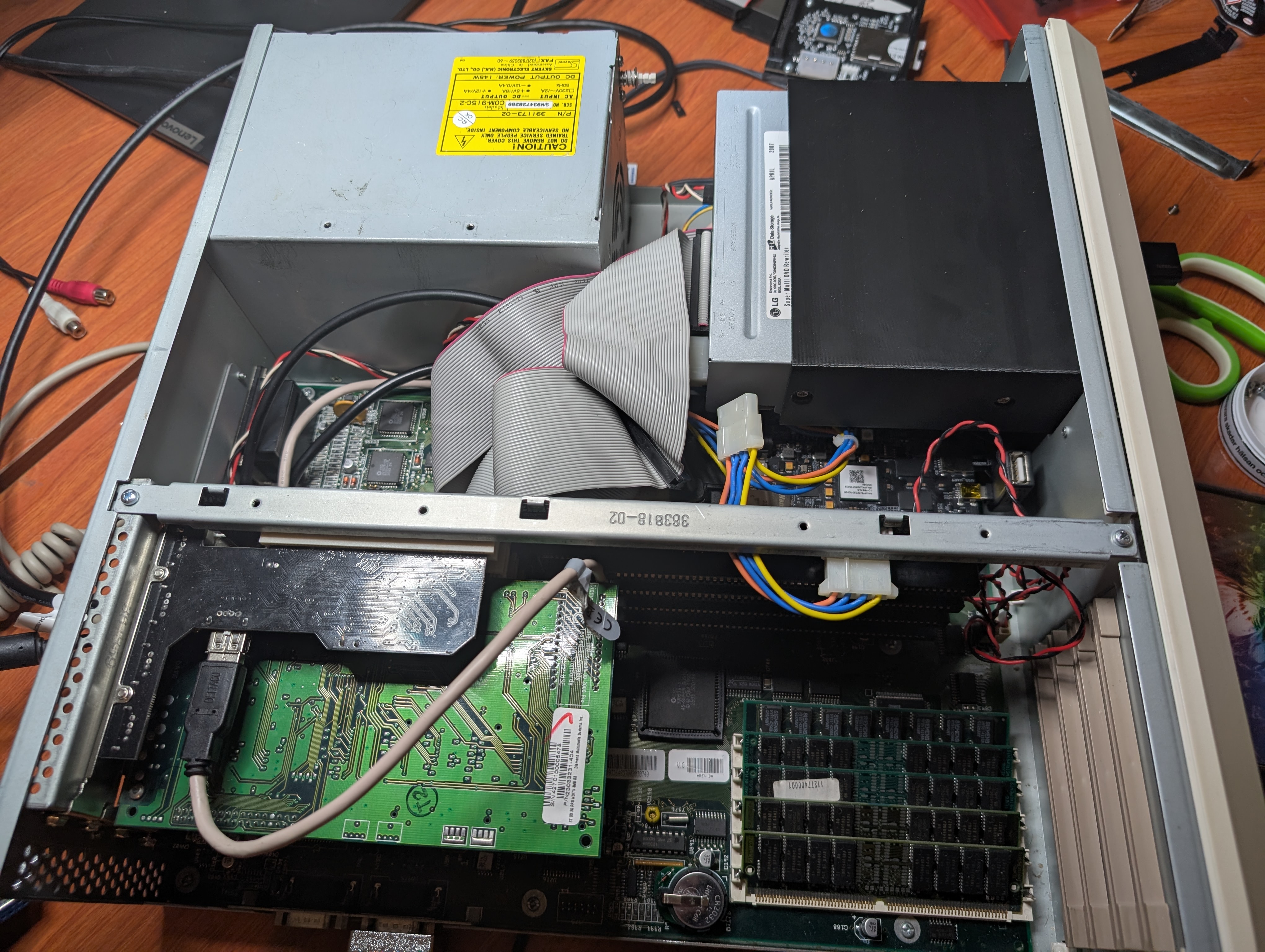
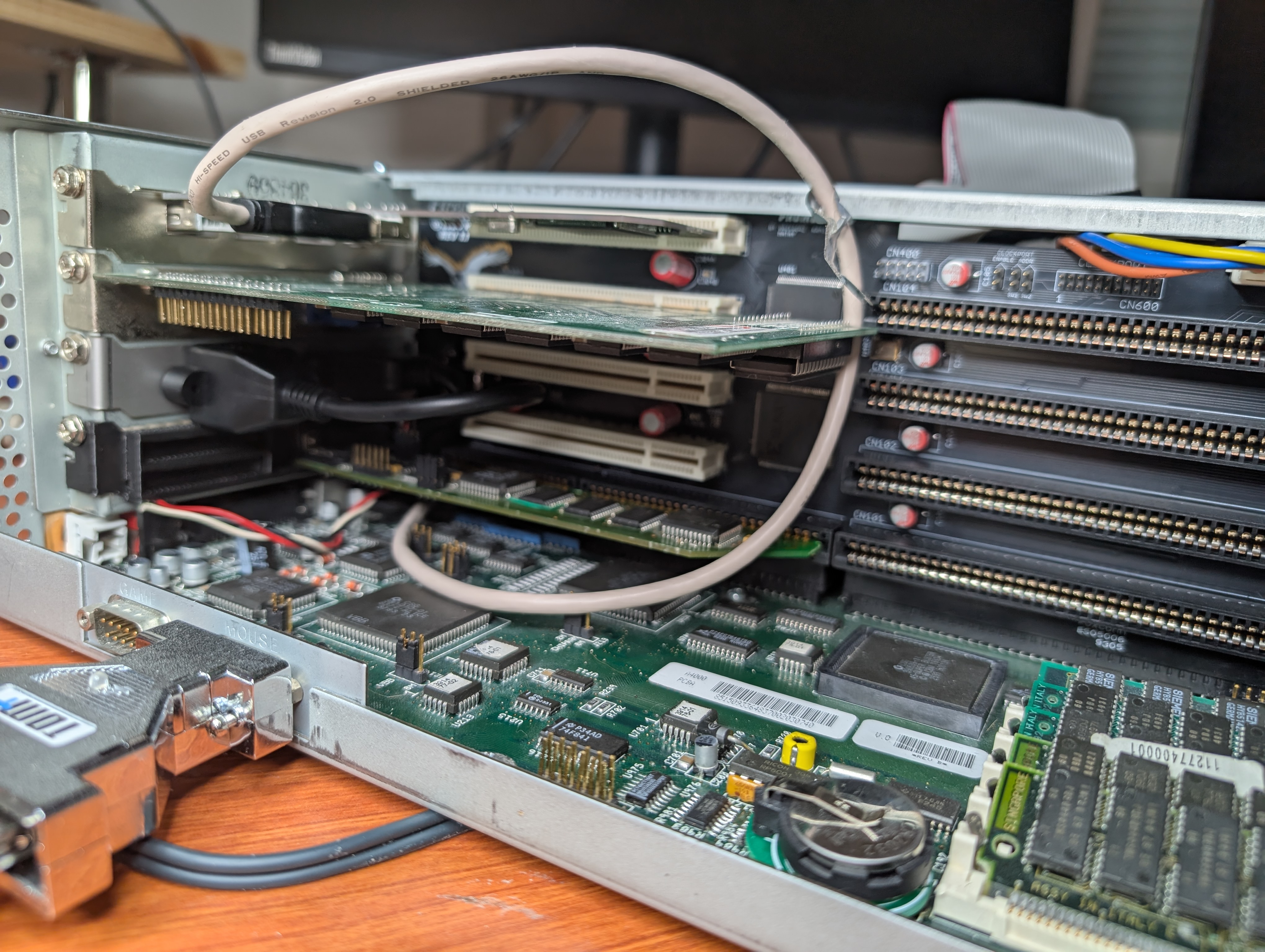
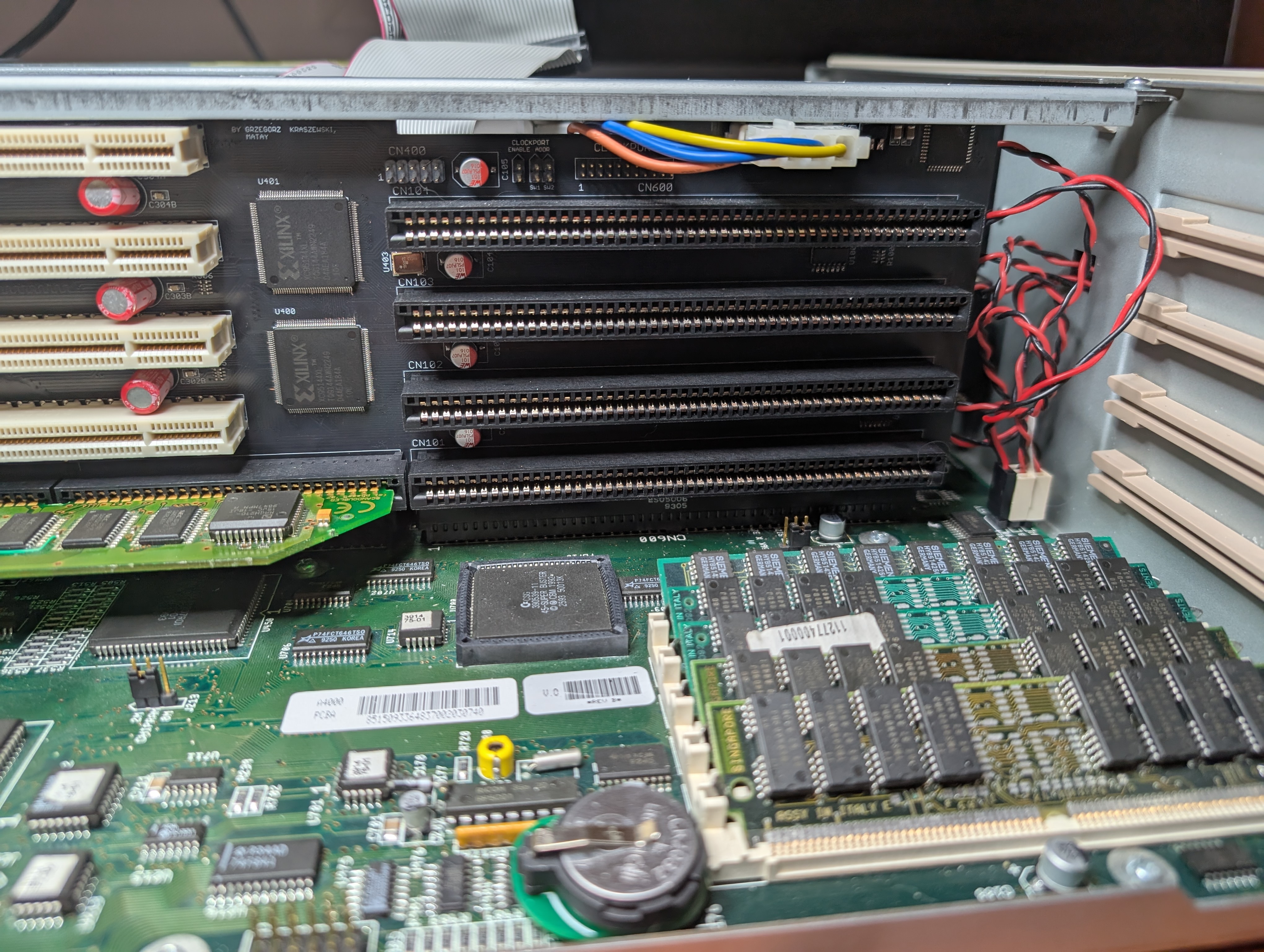
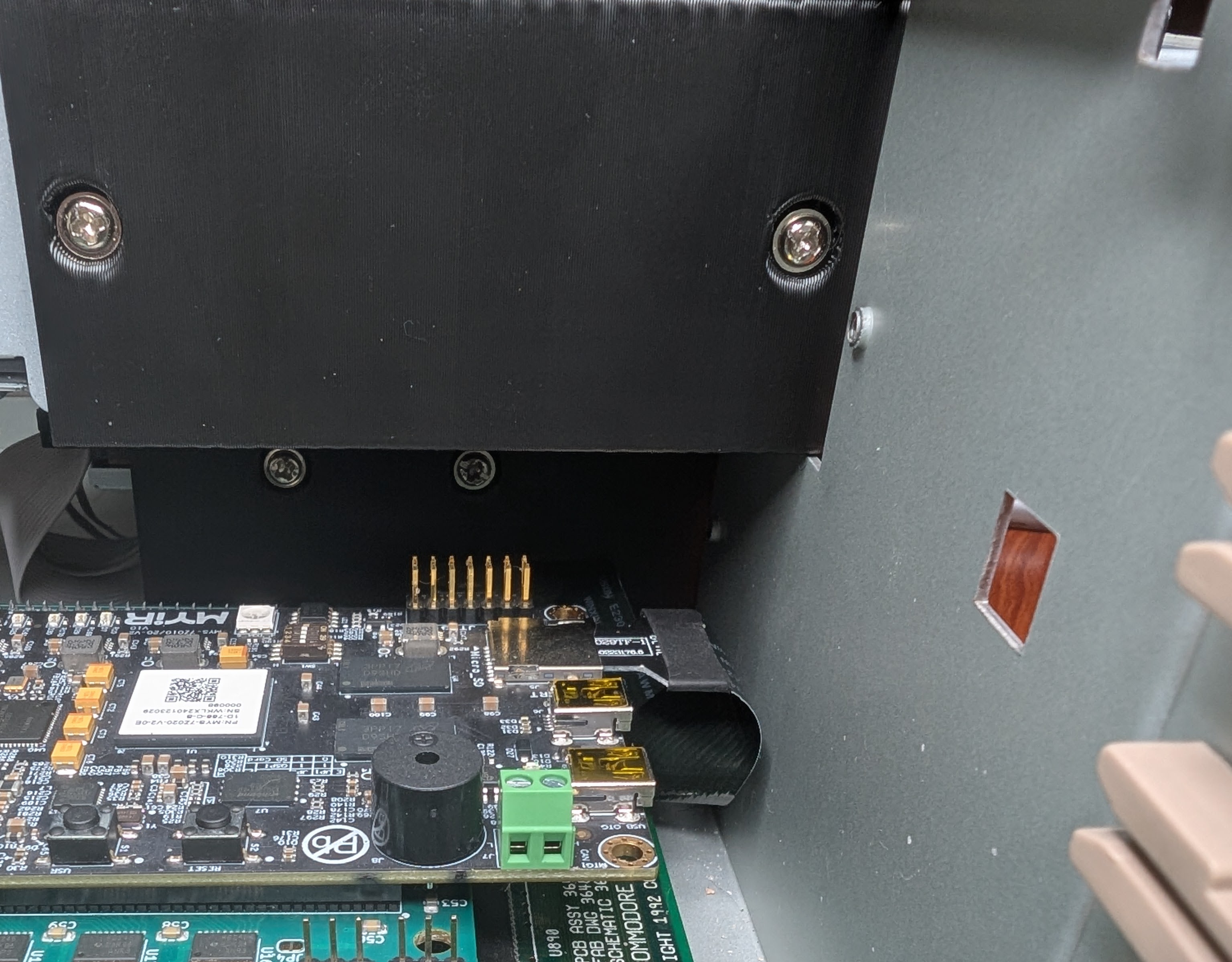
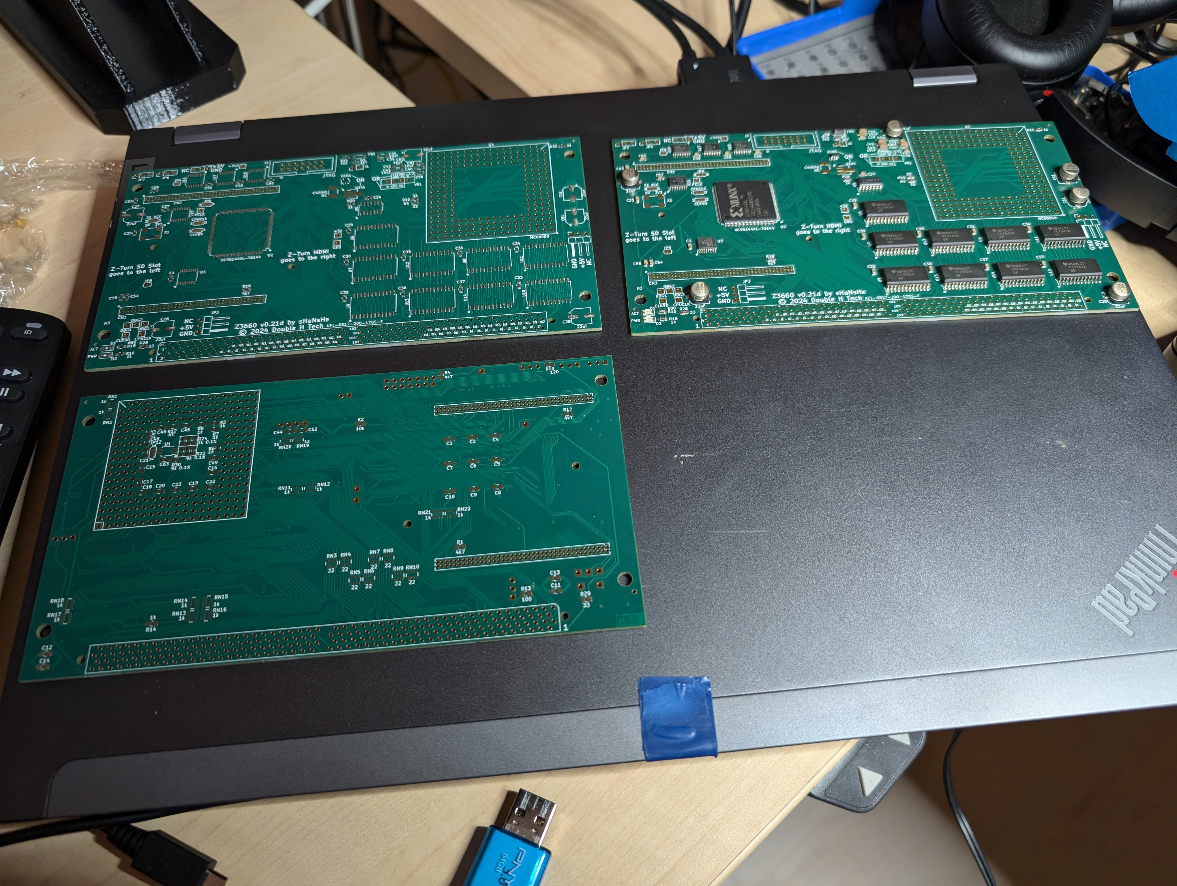
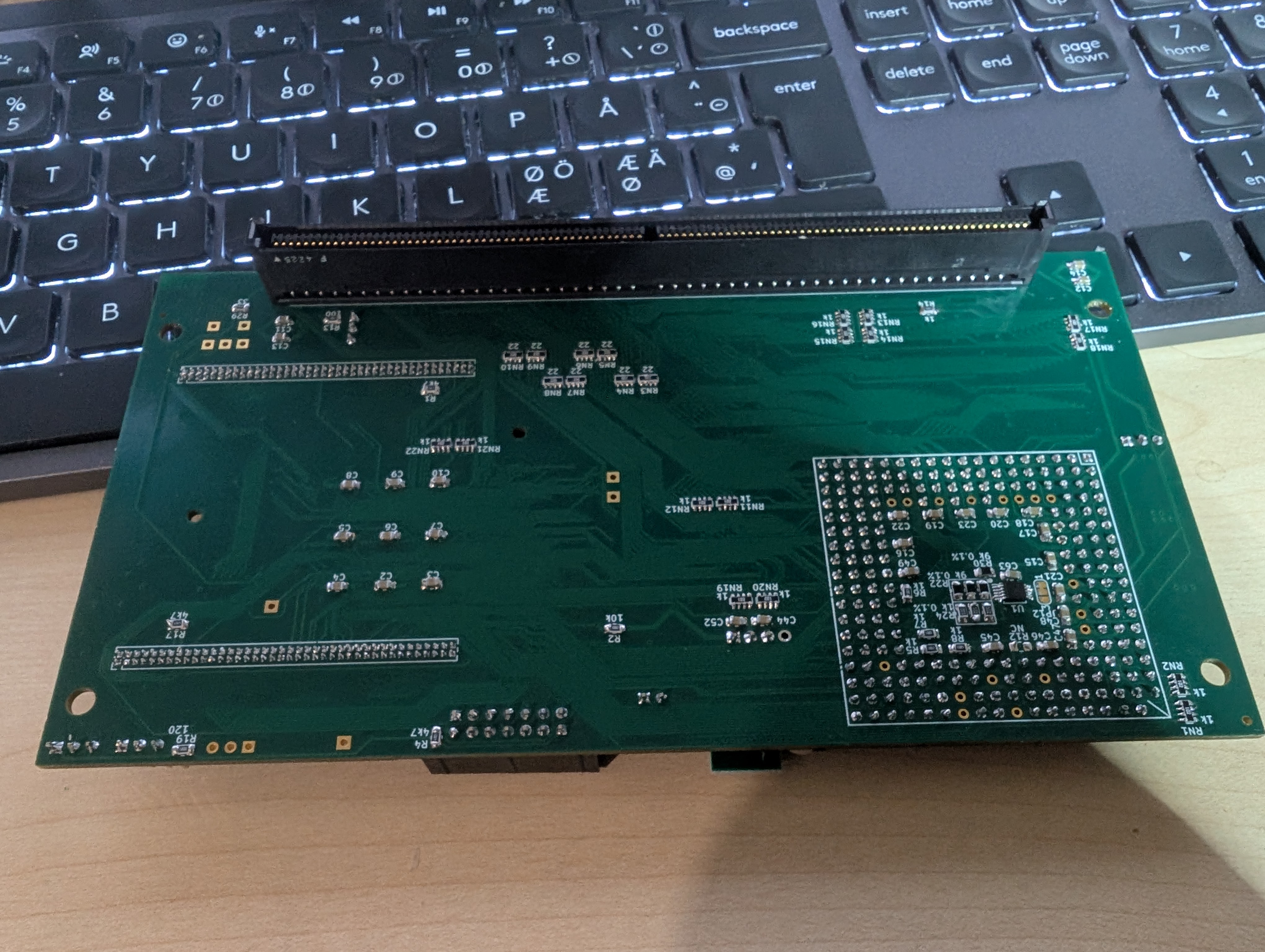
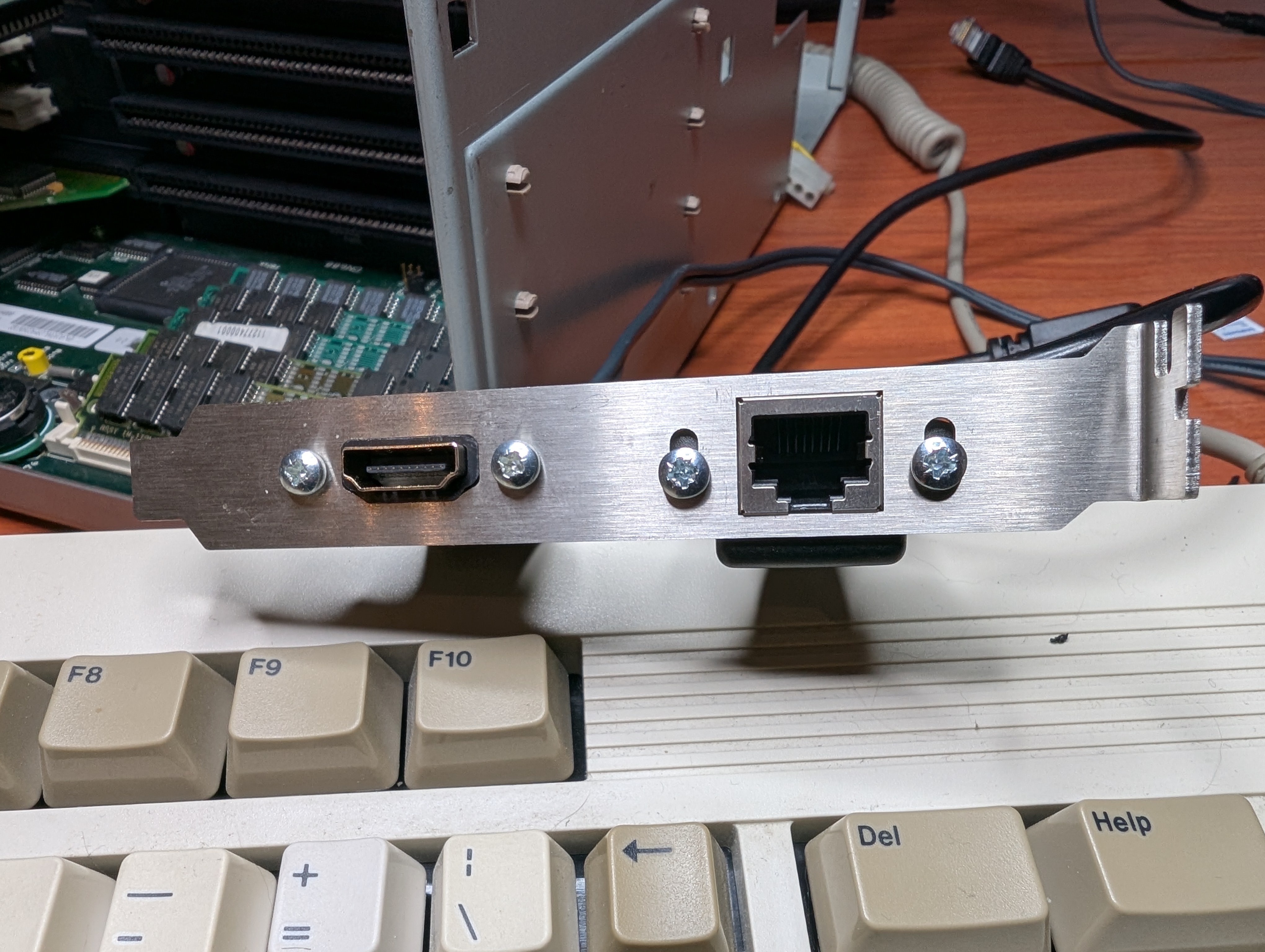
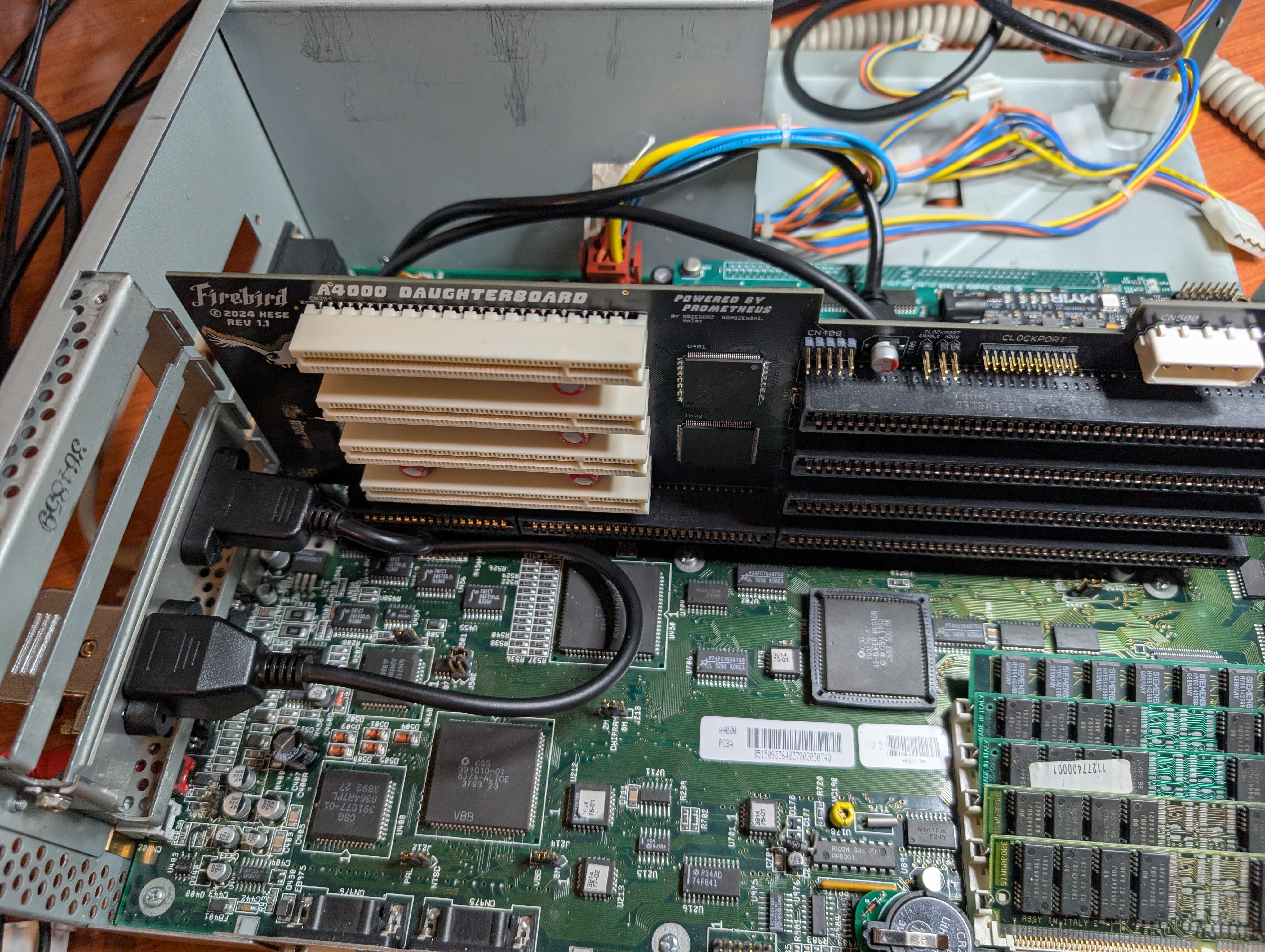
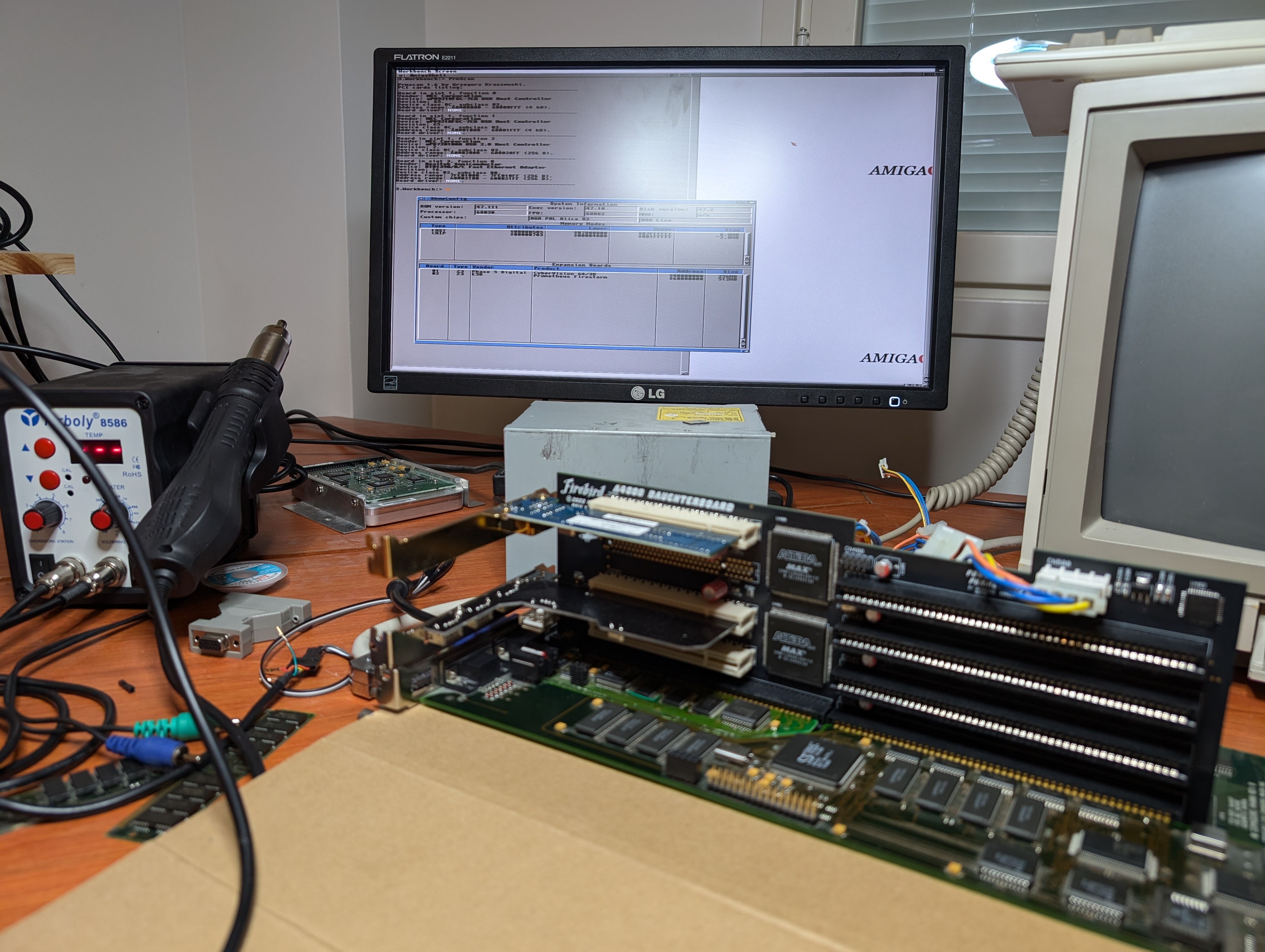
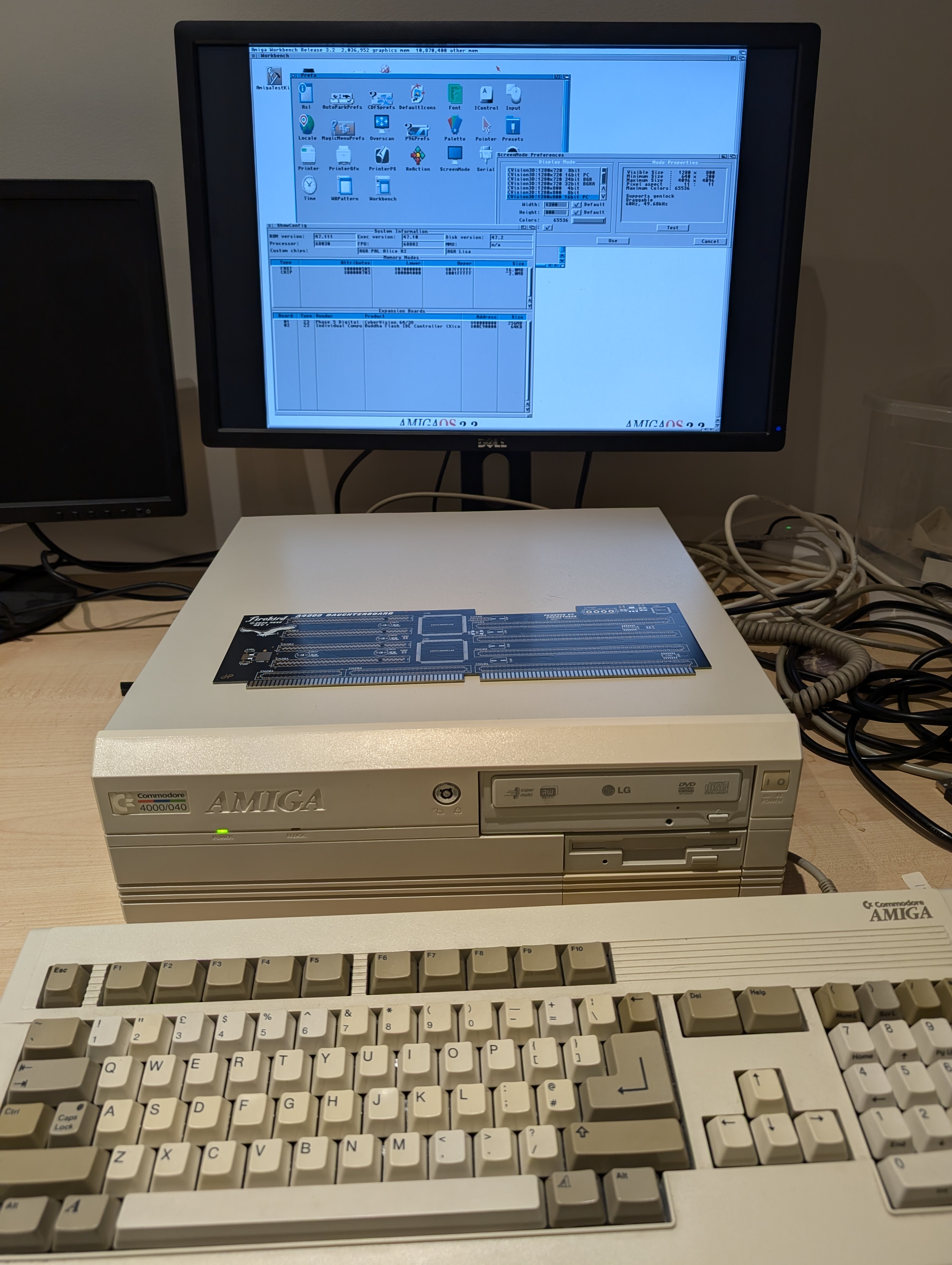
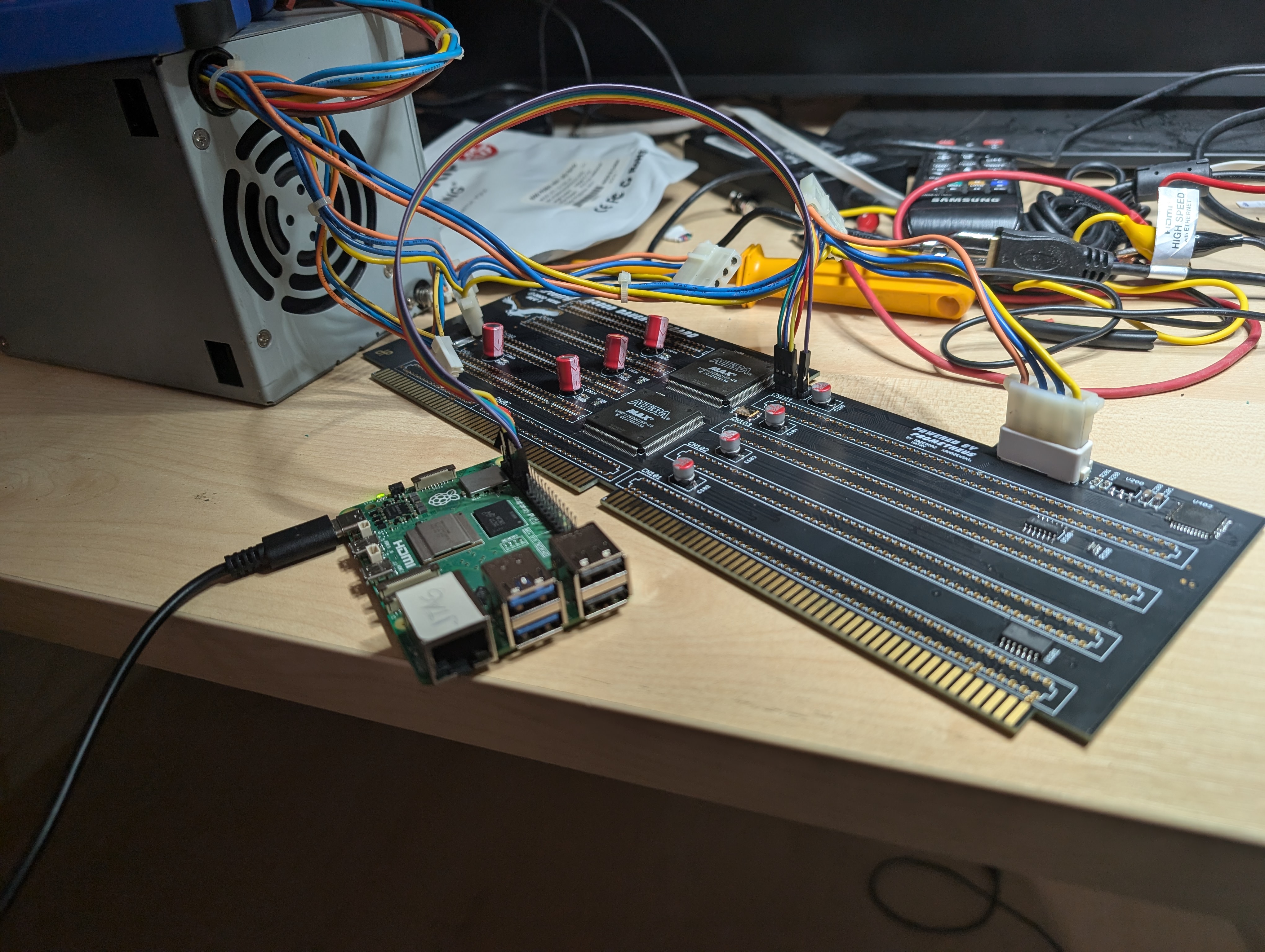
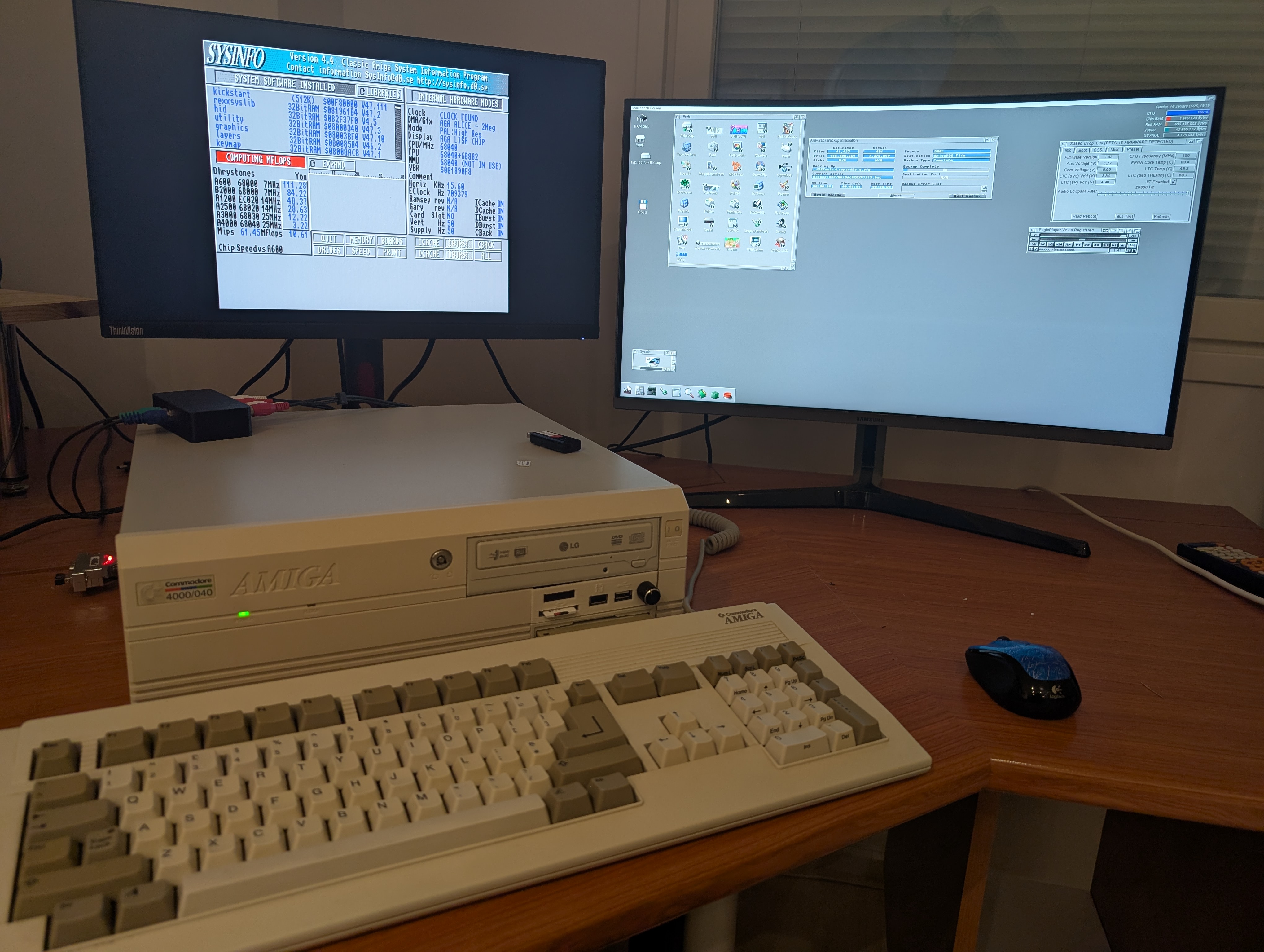
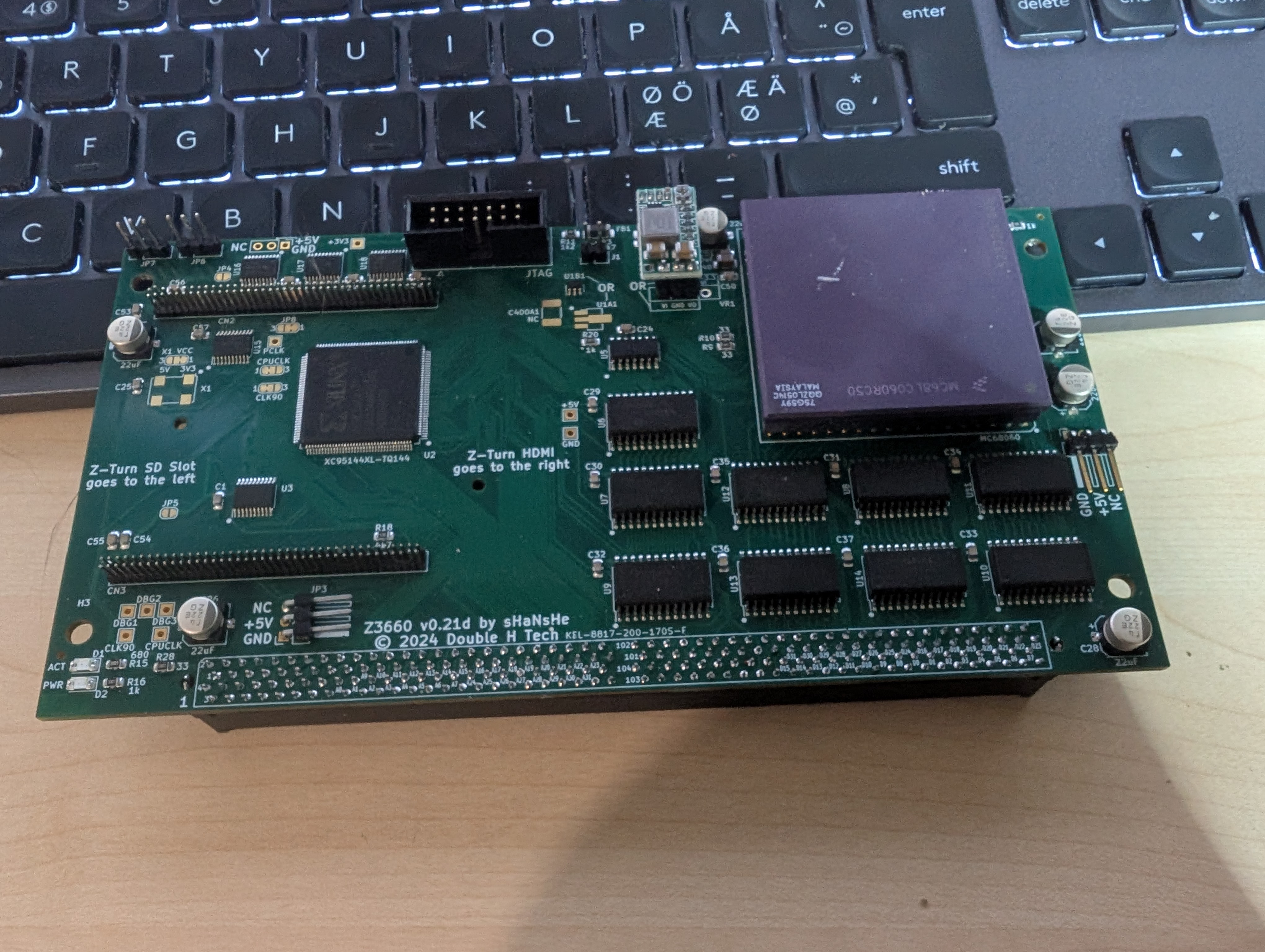
The “unrelated FPGA work” is a small pile of earlier Amiga-era projects on the same rig: programming the Cyclone V SoC for the Z3660 accelerator (upstream repo); bringing up the Firebird PCI daughterboard during my Amiga 4000D restoration; and assembling a MultifixAGA board. Same Pi, same xc3sprog/openFPGALoader toolchain, different bitstreams. So this time, when the C64U was in trouble, the rig was already on the desk.
This is the story of that port, the bug I hit along the way, and the open-source repo it turned into.
What broke
I had been running the Commodore-line c64u_v1.1.0.ue2 firmware happily for a while, and I’d been chasing upstream. Gideon’s master branch has accumulated nice things since 1.1.0 — mouse-pointer support among them — so I’d taken a few stabs at building a C64U-compatible artifact straight off master myself. The C64U target on master needs more toolchain love than my off-the-shelf setup was willing to give it; some attempts fell over at link/pack, and the ones that did produce a flashable .ue2 all had something subtly wrong with the C64-mode handoff.
I flashed one anyway. The result was an interesting half-broken state. The management plane stayed alive — networking was reachable throughout, and once I’d re-poked the HDMI settings through the telnet menu the on-screen menu UI itself looked normal. As far as the Ultimate’s own face was concerned, the device was up.
The problems were below that:
- BASIC handoff hung every time. The C64 side of the device — the whole reason the thing exists — wouldn’t come up. Drop into the menu, try to launch C64 mode, and the device would freeze. No build attempt I made off master ever fixed this; BASIC handoff would always still fail.
- The in-menu
.ue2LOAD path quietly failed. That’s the normal recovery route: load a known-good firmware from a USB stick through the menu. It returned no error and didn’t actually flash anything. The obvious “just flash 1.1.0 back through the front door” path was closed.
This is the canonical “bricked by incompatible firmware” state. The C64U Mark 2 / Elite II hardware family has had a few cases of this in the wild — see GideonZ/1541ultimate#537 and the related PR #636 for the upstream context.
The official recovery path
Gideon’s recovery is a two-stage JTAG procedure that runs entirely in volatile memory — it never touches flash, and a power-cycle reverts everything. The stages are:
-
Load a recovery FPGA bitstream (
u64_mk2_artix.bit) into the on-board Artix-7 fabric. This is just a normal Xilinx 7-series JTAG configuration —xc3sprogandopenFPGALoaderboth speak it natively. Once configured, the FPGA exposes a custom JTAG-AXI bridge via the standard Xilinx USER4 BSCANE2 primitive. -
Talk to that bridge to (a) assert the on-FPGA RISC-V soft-core’s reset, (b) stream a recovery RISC-V firmware image (
ultimate.bin) into DRAM in 16 KB chunks, (c) write a boot-magic word at a specific DRAM address, and (d) release the CPU from reset so it boots from DRAM.
After Stage 2, the device comes up with a working recovery menu on HDMI. From there, you run a normal update.ue2 from a USB stick to permanently restore flash. Until you do that last step, the recovery is volatile — power-cycle and you’re back to the bricked state.
Gideon ships a Python script (recover.py) that does Stage 2 over an FT232H USB-MPSSE bridge via pyftdi. Stage 1 you can do with xc3sprog or openFPGALoader against the same FT232H.
The Raspberry Pi alternative
The Pi JTAG rig on my desk was already wired up for Xilinx programming via the MATRIX Labs xc3sprog fork, using the well-known LinuxJedi 2025 Raspberry Pi JTAG layout. The pinout there matches xc3sprog‘s matrix_creator / gpiod_creator cable definition:
| Pi BCM (board pin) | Signal | C64U P5 pin |
|---|---|---|
| GPIO 17 (pin 11) | TCK | 1 |
| GPIO 4 (pin 7) | TMS | 5 |
| GPIO 22 (pin 15) | TDI | 9 |
| GPIO 27 (pin 13) | TDO | 3 |
| GND (pin 6/9/14/…) | GND | 2 or 10 |
⚠ Don’t connect 3.3V — the C64U powers its JTAG side from its own PSU. Connecting Pi 3.3V to the C64U’s 3.3V rail back-feeds the C64U from the Pi.
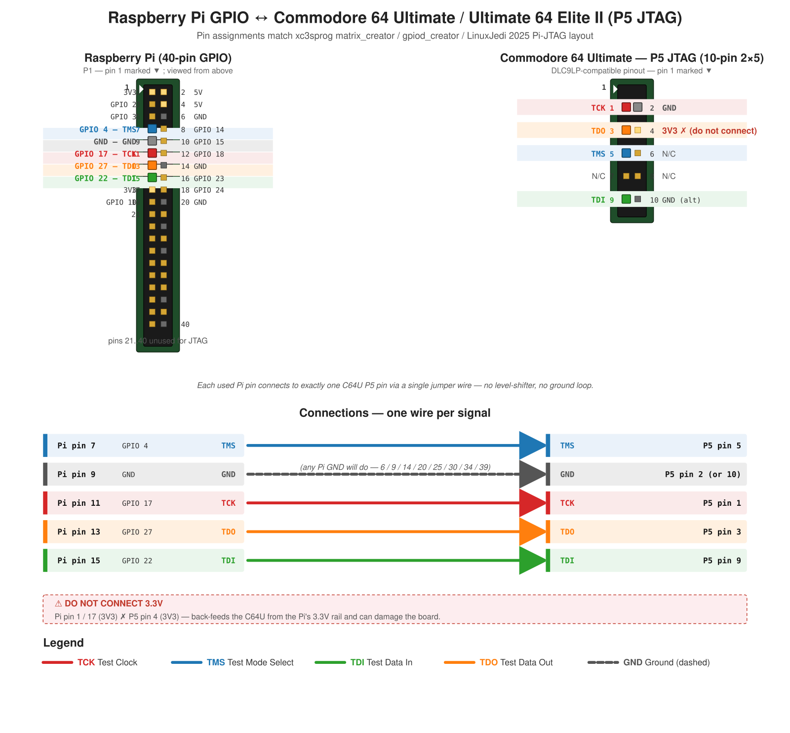
The chain test (Stage 0) was reassuring:
$ xc3sprog -c matrix_creator -j
JTAG loc.: 0  IDCODE: 0x0362c093  Desc:  XC7A50T Rev: A  IR length: 6
That’s the C64U’s Artix-7 IDCODE coming back exactly as expected. Wiring confirmed. Now I just needed Stage 2 — Gideon’s recover.py, ported away from pyftdi to plain Pi GPIO bit-banging.
The port
Worth saying up front: this is where Claude did most of the heavy lifting. Reverse-engineering Gideon’s recover.py and the BSCANE2 user-side protocol cold, working out what the bridge actually expected, mapping the FT232H reference onto a bit-banged GPIO transport — that was Claude leading the analysis and me driving the engineering: integrating, debugging on hardware, deciding what to ship. Where I say “I” in the next two sections, it should mostly read “we”.
Gideon’s recover.py is about 170 lines. The vast majority of it is bridge-protocol code: the BSCANE2 IR opcodes, the DR formats, the address-command structure, the boot-magic semantics. None of that needed to change between FT232H and Pi GPIO — it’s the same JTAG protocol either way.
What did need to change was the transport layer: the JTAG TAP state machine, IR/DR shifts, TDO sampling. That’s what pyftdi was abstracting; on the Pi I had to implement it from scratch on top of RPi.GPIO‘s raw pin operations.
A JtagBitbang class that maintains TAP state and exposes irscan() / drscan_int() / drscan_bytes() was about 120 lines of straightforward TAP-state-machine bookkeeping. Then I dropped Gideon’s protocol layer on top of it almost verbatim.
I deployed it to the Pi, ran the smoke test… and got the right IDCODE. So far so good.
The bug
I ran the full recovery. It completed without errors. ~960 KB streamed to DRAM in about 70 seconds. CPU released from reset. And then…
…nothing. HDMI stayed dark. The C64U was unchanged.
Worse: when I read the bridge’s user-side IDCODE after boot — which Gideon designs to return a deliberate magic value (0xdead1541) once the recovery firmware is running — I got back garbage:
INFO Releasing CPU reset (output 0x00) — RISC-V should now boot from DRAM…
INFO User-side IDCODE: 0xbd5a2a83
0xbd5a2a83 is “the bridge protocol got desynced” garbage. The recovery firmware almost certainly hadn’t booted at all.
The bug took a few hours to find. It comes down to a subtlety in how set_user_ir is supposed to drive the JTAG TAP state machine.
The bridge expects a sequence like this: USER4 IRSCAN → a 5-bit DR write that selects the inner bridge IR → USER4 IRSCAN → enter Shift-DR, shift a single mode-bit “0” to mark “what follows is data”, then continue shifting the payload in the same Shift-DR run, finally exiting with one Update-DR at the end. The bridge sees the mode bit and the payload as one continuous DR transaction committed by a single Update-DR.
My initial port was doing it the obvious-looking way: shift the mode bit, exit Shift-DR (Update-DR + go back to RTI), then start a fresh Shift-DR for the payload. That produces two Update-DR events instead of one, and the bridge interprets the second drscan’s payload as if it were bridge-IR, not data. Everything downstream was operating on the wrong register.
The fix is one parameter change. set_user_ir now leaves the TAP in Shift-DR (no exit), and the next drscan continues from there:
def set_user_ir(self, ir):
    self.j.irscan(XILINX_USER4)
    self.j.drscan_int((ir << 1) | 1, 5, exit_to_rti=True)
    self.j.irscan(XILINX_USER4)
    # Enter Shift-DR, shift the '0' mode bit, STAY in Shift-DR.
    self.j.drscan_int(0, 1, exit_to_rti=False)

def read_user_dr(self, n_bits):
    # Continues from Shift-DR. One final Update-DR commits the full
    # mode-bit + n_bits to the bridge.
    return self.j.drscan_int(0, n_bits, exit_to_rti=True)
pyftdi handles this implicitly via its higher-level shift_register() API; it never exposes the intermediate Update-DR boundary, so Gideon’s original script doesn’t need to think about it. On a hand-rolled bit-banger that can pulse TMS=1 too eagerly on the last bit, it bites you. I wrote up the full TAP-state-machine analysis with a Mermaid diagram in docs/PROTOCOL.md for anyone porting BSCANE2-based recovery scripts to other JTAG transports — this is exactly the kind of detail that’s invisible in the upstream code but critical when you change layers.
The recovery itself
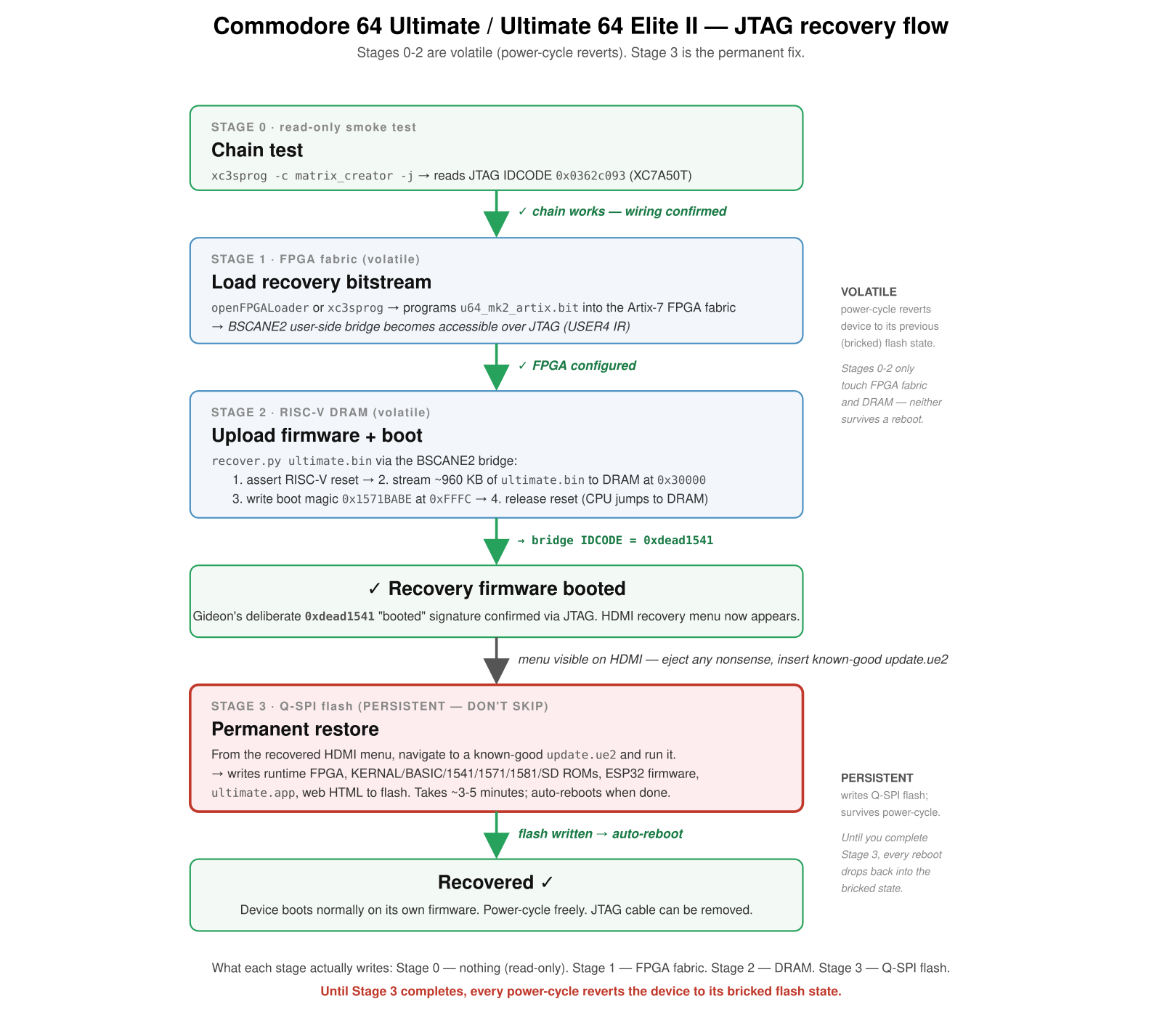
With the bug fixed, the recovery ran clean:
INFO IDCODE: 0x0362c093
INFO User-side IDCODE: 0x0362c093
INFO Asserting CPU reset (output 0x80)…
INFO Uploading ./ultimate.bin to DRAM at 0x00030000…
INFO Uploaded chunk -> next addr 0x00040000, total 16384 bytes
…
INFO Upload complete: 984040 bytes
INFO Writing boot magic at 0x0000fff8: addr=0x00030000 sig=0x1571babe
INFO Releasing CPU reset (output 0x00) — RISC-V should now boot from DRAM…
INFO User-side IDCODE: 0xdead1541
INFO Stage 2 done. Watch the C64U: HDMI/menu should come up shortly.
0xdead1541 is Gideon’s deliberate “recovery firmware booted” signature. As soon as that came back, HDMI lit up:
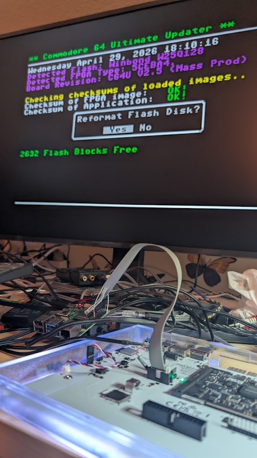
The recovery menu detected the board correctly — C64U V2.5 (Mass Prod) — and offered to reformat the flash disk. End-to-end Stage 2 runtime was about 70 seconds; total time including Stage 0 chain test and Stage 1 FPGA load was under 2 minutes.
But the recovery so far was only in DRAM. The flash was still bricked. Power-cycling at this point would lose everything.
The flash restoration
To make the recovery permanent, I navigated to a known-good c64u_v1.1.0.ue2 on a USB stick from inside the recovered HDMI menu and ran it. That’s the official update flow, just running on top of a temporarily-recovered device instead of a working one.
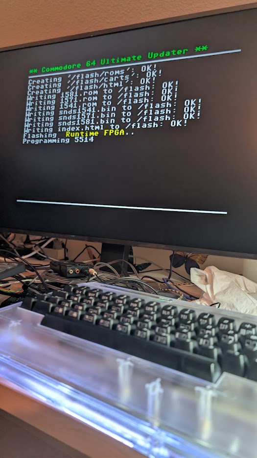
The Updater wrote everything to flash: the runtime FPGA bitstream, the kernal/BASIC/1541/1571/1581/SD ROMs, the ESP32 firmware, the Ultimate application, the management web HTML. About 3–5 minutes, then auto-reboot.
After reboot, the device came up on its own permanently-flashed firmware. JTAG cable came off. Power-cycled it a few times to be sure. All good.
Takeaways
A few things worth pulling out of this experience:
-
Bricks aren’t bricks. As long as the JTAG header on the board is functional and the FPGA itself isn’t physically dead, the device is recoverable. Flash being garbage just means flash needs to be bypassed via volatile JTAG-loaded code, then rewritten from inside that recovered environment.
-
FPGA bitstream versions matter — but you can JTAG-load any compatible recovery bitstream regardless of what’s currently in flash. The recovery FPGA + RISC-V image pair from upstream’s
recovery/u64ii/is what makes this work on the C64 Ultimate hardware family. -
Any FT232H-based JTAG recovery script can probably be ported to a Pi, if the protocol underneath is just standard IRSCAN/DRSCAN sequences. The non-obvious part is the TAP state machine — specifically how aggressively your transport pulses TMS to exit Shift-DR. Anything where the upstream protocol assumes “stay in Shift-DR across calls” needs a transport that allows it.
-
Diagnose by checking the bridge IDCODE. Gideon’s
0xdead1541signature is brilliant — it gives you a one-bit answer to “did the recovery firmware actually boot?” If you don’t get that back, your protocol or wiring is wrong, regardless of what the upload step claimed.
A small Bookworm gotcha (GPIO library)
One thing tripped me up early. On Raspberry Pi OS Bookworm (Debian 12), my first instinct was to use libgpiod’s Python bindings — they’re the modern, Pi-5-friendly choice. But:
apt install python-gpioddoesn’t exist. The package is namedpython3-libgpiod.- The PyPI
gpiodpackage’s API changed significantly between v1 and v2, and the v1 examples I had on hand didn’t drop in cleanly to the v2 binding shipped on Bookworm.
I fell back to the older RPi.GPIO library via apt install python3-rpi.gpio, which the Raspberry Pi Foundation has specifically patched for Bookworm. That worked first try. Do not pip install RPi.GPIO on Bookworm — the upstream PyPI version is older and broken under the newer kernel; only the apt build is current.
For a future Pi-5 backend, lgpio or python3-libgpiod v2 would be the right path; PRs welcome.
What’s next
Post-recovery, the device is back on 1.1.0 stable — but the original goal hasn’t moved: I want a build off Gideon’s master running on the C64U, with the mouse-pointer additions and everything else that’s landed upstream since 1.1.0. The next round is figuring out the proper build recipe for the C64U target on current master — what the toolchain actually expects, which configuration knobs need to be flipped, and where the C64-mode handoff is going wrong on my own builds. Ideally I’d have it nailed down before the next official Commodore firmware drop makes the question moot.
Code & credits
The full recovery tool is open source: github.com/jusii/ultimate64-jtag-recovery-pi (GPLv3, matching upstream). Tagged release: v1.0.0.
The repo includes:
recover.py— Stage 2 (DRAM upload + boot)soft_reset.py— bonus utility, soft-resets the recovered RISC-V via JTAG without redoing the full sequence- shell wrappers for Stage 0 (chain test) and Stage 1 (FPGA load)
- Verbatim copies of upstream’s
u64_mk2_artix.bitandultimate.binrecovery artifacts (with refresh instructions in the README) - The wiring diagram and recovery-flow diagram embedded above
docs/PROTOCOL.mdwith the BSCANE2 user-side protocol breakdown and the TAP-state-machine analysis
This work would not have been possible without:
- Gideon Zweijtzer (@GideonZ) — designer of the entire 1541 Ultimate firmware family, author of the original
recover.py, designer of the BSCANE2 user-side recovery bridge. The protocol layer in my repo is byte-faithful to his FT232H reference implementation; only the JTAG transport was reimplemented. - LinuxJedi — whose Raspberry Pi JTAG Programming 2025 Edition guide documents the Pi-as-Xilinx-programmer setup and the GPIO pin layout I ended up using as default.
- MATRIX Labs
xc3sprogfork —sysfscreatorcable definition, source of the default pinout. - Gee-64, robotfreak, and the contributors to upstream issue #537 and PR #636.
- Claude — did most of the reverse-engineering of Gideon’s
recover.pyand the BSCANE2 user-side protocol, including the TAP-state-machine analysis that uncovered the Update-DR bug.
If you have a similar hardware mishap, the procedure is documented step-by-step in the repo README. This Pi port is unofficial and isn’t endorsed by upstream. If you want to share that it worked, compare hardware revisions, or report a problem, drop a comment here on the blog or open an issue/discussion on the recovery repo.